Tuesday, 3 October 2017

Arduino 25v DC Voltage Sensor

Arduino 25v DC Voltage Sensor


In arduino the input voltage limited to 5v DC voltage. If your want to measure higher voltage though arduino, then we will need to use voltage divider method.

This voltage sensor is use the method of voltage divider rule from which we can measure the voltage up to 25v. It is fundamentally a voltage divider using 30k and 7k ohm resistor.

This sensor is restricted to 25v DC voltage. For measure more than 25v we have to create another sensor by using voltage divider rule.

Basic Senor Diagram:


Inputs

  • GND –  This is where you connect the low side of the voltage you are measuring.   Caution! : This is the same electrical point as your Arduino ground. Or to connect GND to GND r negative of supply.
  • VCC:  The is where you connect the high side of  the voltage you are measuring. Or to connect VCC to the positive terminal or point of supply.

Outputs

  • S:  This connects to your Arduino analog input. E.g a0, a1, a2 ( a series of ardiuno)
  • – (or minus):  This connects to your Arduino ground.
  • +:  This is not connected.  It does absolutely nothing.

Where to buy?

You can order us, to book your order inbox on Facebook or mail us.

Facebook: https://web.facebook.com/electronic.enginer
Mail: electronicengineerads@gmail.com

Schematic

The schematic of this voltage sensor is quite so easy as it mentioned that it is the combination of two resistor for using voltage divider rule.


The Connections

Connect any DC voltage source which is not more than 25v. Here, we use 9v battery source connect to GND and VCC and arduino is connected to S and -(minus) as show in figure


The Sketch

The following code upload in the arduino and you can see the measured voltage at Arduino serial monitoring.

/*
DC Voltmeter Using a Voltage Divider

*/

int analogInput = A1;
float vout = 0.0;
float vin = 0.0;
float R1 = 30000.0; //
float R2 = 7500.0; //
int value = 0;
void setup(){
pinMode(analogInput, INPUT);
Serial.begin(9600);
Serial.print("DC VOLTMETER");
}
void loop(){
// read the value at analog input
value = analogRead(analogInput);
vout = (value * 5.0) / 1024.0; // see text
vin = vout / (R2/(R1+R2));
Serial.print("INPUT V= ");
Serial.println(vin,2);
delay(500);
}

Saturday, 30 September 2017

Digital Clock Without Microcontroller

Digital Clock Without Microcontroller 


This circuit  is designed to display the time in hours and minutes format, and is wired such that it functions in 24-hour mode. For this purpose, this circuit make use of six 74LS90 decade counters (in figure,IC1 through IC6), four 74LS247 BCD to 7-segment decoders/drivers (IC7 through IC10) and four LT S542 common anode displays (DIS1 through DIS4). In addition, passive components like few resistors, capacitors and push-to-on switches are employed. A 1Hz clock is used to supply the input to the IC1 through pin 14, (1 Hz clock generator circuit is shown in button of article). The output obtained from both of the above mentioned circuits become more accurate with the fact that both circuit take advantage of   32.768kHz quartz crystal.

Sunday, 5 February 2017

7 SEGMENT DISPLAY COUNTER


Saturday, 11 June 2016

INTERFACE A 7-SEGMENT DISPLAY PAIR WITH PORT 0


INTERFACE A 7-SEGMENT DISPLAY PAIR WITH PORT 0


In this project we will show how to interface 7_segment display with port 0 of microcontroller.


Steps:

First of all make your microcontroller active by connecting the crystal from pin number 18 and 19(see in figure 2) 
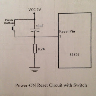
Set the reset button from pin 9 as shown in figure 3.
Make the controller in working order as show in figure 4, then connect an LED through resistor to pin of port 1.0
Write a program of interface 7_segment display with port 0 of microcontroller in assembly language.
Burn the assembly language program in microcontroller through universal programmer.
You can see th wave form on oscilloscope.

Circuit Diagram:

TURNING ON AND OFF LED
pic configuration of ATML 89S52


TURNING ON AND OFF LED
Attachment of crystall figure number 2
TURNING ON AND OFF LED
Reset button figure no.3
TURNING ON AND OFF LED
Working condition of microcontroller figure 4


connection of 7-segment display

If we want to connect more than one 7 segment

7 Segment Display

Assembly Language Program :


ORG 00H


MAIN:


MOV P2,#10H


MOV P0,#3FH


CALL DELAY


MOV P0,#3FH


CALL DELAY


MOV P0,#06H


CALL DELAY


MOV P0,#5BH


CALL DELAY


MOV P0,#4FH


CALL DELAY


MOV P0,#66H


CALL DELAY


MOV P0,#6DH


CALL DELAY


MOV P0,#7DH


CALL DELAY


MOV P0,#07H


CALL DELAY


MOV P0,#6FH


CALL DELAY


MOV P0,#77H


CALL DELAY


MOV P0,#7CH


CALL DELAY


MOV P0,#39H


CALL DELAY


MOV P0,#5EH


CALL DELAY


MOV P0,#79H


CALL DELAY


MOV P0,#71H


CALL DELAY


MOV P2,#20H ; NEXT 7-SEGMENT PAIR ON AND FIRST CLOSE


MOV P0,#3FH


CALL DELAY


MOV P0,#3FH


CALL DELAY


MOV P0,#06H


CALL DELAY


MOV P0,#5BH


CALL DELAY


MOV P0,#4FH


CALL DELAY


MOV P0,#66H


CALL DELAY


MOV P0,#6DH


CALL DELAY


MOV P0,#7DH


CALL DELAY


MOV P0,#07H


CALL DELAY


MOV P0,#6FH


CALL DELAY


MOV P0,#77H


CALL DELAY


MOV P0,#7CH


CALL DELAY


MOV P0,#39H


CALL DELAY


MOV P0,#5EH


CALL DELAY


MOV P0,#79H


CALL DELAY


MOV P0,#71H


CALL DELAY


JMP MAIN


DELAY:MOV R3,#10  ; DELAY IN DISPLAY OF 1 SECOND


LOOP0:MOV R2,#100


LOOP1:MOV R1,#2


LOOP2:MOV R2,#230


LOOP3:DJNZ R0,LOOP3


DJNZ R1,LOOP2


DJNZ R2,LOOP1


DJNZ R3,LOOP0


RET

  Note: This is a program of 2 & segment display, so we can write 3 r 4 display too.


For any question comment below or click here for further information

USING LED PAIR FOR COUNTING FROM 0000 TO 1111


USING LED PAIR FOR COUNTING FROM 0000 TO 1111

LED bar start blinking in a sequence from 0000 to 1111, step by step with some delay.


Steps:

First of all make your microcontroller active by connecting the crystal from pin number 18 and 19(see in figure 2) 
Set the reset button from pin 9 as shown in figure 3.
Make the controller in working order as show in figure 4, then connect an LED through resistor to pin of port 1.0
Write a program of LED bar start blinking in a sequence from 0000 to 1111, step by step with some delay. in assembly language.
Burn the assembly language program in microcontroller through universal programmer.
You can see th wave form on oscilloscope.

Circuit Diagram:

TURNING ON AND OFF LED
pic configuration of ATML 89S52

TURNING ON AND OFF LED
Attachment of crystall figure number 2
TURNING ON AND OFF LED
Reset button figure no.3
TURNING ON AND OFF LED
Working condition of microcontroller figure 4
TURNING ON AND OFF LED
LED connection

Assembly Language Program :


ORG 00H
MAIN :
MOV P1,#0FFH
CLR A
PROG:
CPL  A
MOV P1,A
CPL A
INC A
CALL DELAY
CJNE A,#10H,PROG
JMP MAIN
DELAY:MOV R3,#10
LOOP0:MOV R2,#100
LOOP1:MOV R1,#2
LOOP2:MOV R2,#230
LOOP3:DJNZ R0,LOOP3
DJNZ R1,LOOP2
DJNZ R2,LOOP1
DJNZ R3,LOOP0
RET

For any question comment below or click here for further information