Saturday 11 June 2016

INTERFACE A 7-SEGMENT DISPLAY PAIR WITH PORT 0


INTERFACE A 7-SEGMENT DISPLAY PAIR WITH PORT 0


In this project we will show how to interface 7_segment display with port 0 of microcontroller.


Steps:

First of all make your microcontroller active by connecting the crystal from pin number 18 and 19(see in figure 2) 
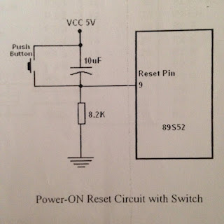
Set the reset button from pin 9 as shown in figure 3.
Make the controller in working order as show in figure 4, then connect an LED through resistor to pin of port 1.0
Write a program of interface 7_segment display with port 0 of microcontroller in assembly language.
Burn the assembly language program in microcontroller through universal programmer.
You can see th wave form on oscilloscope.

Circuit Diagram:

TURNING ON AND OFF LED
pic configuration of ATML 89S52


TURNING ON AND OFF LED
Attachment of crystall figure number 2
TURNING ON AND OFF LED
Reset button figure no.3
TURNING ON AND OFF LED
Working condition of microcontroller figure 4


connection of 7-segment display

If we want to connect more than one 7 segment

7 Segment Display

Assembly Language Program :


ORG 00H


MAIN:


MOV P2,#10H


MOV P0,#3FH


CALL DELAY


MOV P0,#3FH


CALL DELAY


MOV P0,#06H


CALL DELAY


MOV P0,#5BH


CALL DELAY


MOV P0,#4FH


CALL DELAY


MOV P0,#66H


CALL DELAY


MOV P0,#6DH


CALL DELAY


MOV P0,#7DH


CALL DELAY


MOV P0,#07H


CALL DELAY


MOV P0,#6FH


CALL DELAY


MOV P0,#77H


CALL DELAY


MOV P0,#7CH


CALL DELAY


MOV P0,#39H


CALL DELAY


MOV P0,#5EH


CALL DELAY


MOV P0,#79H


CALL DELAY


MOV P0,#71H


CALL DELAY


MOV P2,#20H ; NEXT 7-SEGMENT PAIR ON AND FIRST CLOSE


MOV P0,#3FH


CALL DELAY


MOV P0,#3FH


CALL DELAY


MOV P0,#06H


CALL DELAY


MOV P0,#5BH


CALL DELAY


MOV P0,#4FH


CALL DELAY


MOV P0,#66H


CALL DELAY


MOV P0,#6DH


CALL DELAY


MOV P0,#7DH


CALL DELAY


MOV P0,#07H


CALL DELAY


MOV P0,#6FH


CALL DELAY


MOV P0,#77H


CALL DELAY


MOV P0,#7CH


CALL DELAY


MOV P0,#39H


CALL DELAY


MOV P0,#5EH


CALL DELAY


MOV P0,#79H


CALL DELAY


MOV P0,#71H


CALL DELAY


JMP MAIN


DELAY:MOV R3,#10  ; DELAY IN DISPLAY OF 1 SECOND


LOOP0:MOV R2,#100


LOOP1:MOV R1,#2


LOOP2:MOV R2,#230


LOOP3:DJNZ R0,LOOP3


DJNZ R1,LOOP2


DJNZ R2,LOOP1


DJNZ R3,LOOP0


RET

  Note: This is a program of 2 & segment display, so we can write 3 r 4 display too.


For any question comment below or click here for further information

0 comments:

Post a Comment