Saturday 11 June 2016

INTERFACE A 7-SEGMENT DISPLAY PAIR WITH PORT 0


INTERFACE A 7-SEGMENT DISPLAY PAIR WITH PORT 0


In this project we will show how to interface 7_segment display with port 0 of microcontroller.


Steps:

First of all make your microcontroller active by connecting the crystal from pin number 18 and 19(see in figure 2) 
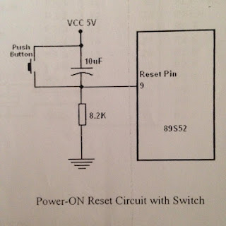
Set the reset button from pin 9 as shown in figure 3.
Make the controller in working order as show in figure 4, then connect an LED through resistor to pin of port 1.0
Write a program of interface 7_segment display with port 0 of microcontroller in assembly language.
Burn the assembly language program in microcontroller through universal programmer.
You can see th wave form on oscilloscope.

Circuit Diagram:

TURNING ON AND OFF LED
pic configuration of ATML 89S52


TURNING ON AND OFF LED
Attachment of crystall figure number 2
TURNING ON AND OFF LED
Reset button figure no.3
TURNING ON AND OFF LED
Working condition of microcontroller figure 4


connection of 7-segment display

If we want to connect more than one 7 segment

7 Segment Display

Assembly Language Program :


ORG 00H


MAIN:


MOV P2,#10H


MOV P0,#3FH


CALL DELAY


MOV P0,#3FH


CALL DELAY


MOV P0,#06H


CALL DELAY


MOV P0,#5BH


CALL DELAY


MOV P0,#4FH


CALL DELAY


MOV P0,#66H


CALL DELAY


MOV P0,#6DH


CALL DELAY


MOV P0,#7DH


CALL DELAY


MOV P0,#07H


CALL DELAY


MOV P0,#6FH


CALL DELAY


MOV P0,#77H


CALL DELAY


MOV P0,#7CH


CALL DELAY


MOV P0,#39H


CALL DELAY


MOV P0,#5EH


CALL DELAY


MOV P0,#79H


CALL DELAY


MOV P0,#71H


CALL DELAY


MOV P2,#20H ; NEXT 7-SEGMENT PAIR ON AND FIRST CLOSE


MOV P0,#3FH


CALL DELAY


MOV P0,#3FH


CALL DELAY


MOV P0,#06H


CALL DELAY


MOV P0,#5BH


CALL DELAY


MOV P0,#4FH


CALL DELAY


MOV P0,#66H


CALL DELAY


MOV P0,#6DH


CALL DELAY


MOV P0,#7DH


CALL DELAY


MOV P0,#07H


CALL DELAY


MOV P0,#6FH


CALL DELAY


MOV P0,#77H


CALL DELAY


MOV P0,#7CH


CALL DELAY


MOV P0,#39H


CALL DELAY


MOV P0,#5EH


CALL DELAY


MOV P0,#79H


CALL DELAY


MOV P0,#71H


CALL DELAY


JMP MAIN


DELAY:MOV R3,#10  ; DELAY IN DISPLAY OF 1 SECOND


LOOP0:MOV R2,#100


LOOP1:MOV R1,#2


LOOP2:MOV R2,#230


LOOP3:DJNZ R0,LOOP3


DJNZ R1,LOOP2


DJNZ R2,LOOP1


DJNZ R3,LOOP0


RET

  Note: This is a program of 2 & segment display, so we can write 3 r 4 display too.


For any question comment below or click here for further information

USING LED PAIR FOR COUNTING FROM 0000 TO 1111


USING LED PAIR FOR COUNTING FROM 0000 TO 1111

LED bar start blinking in a sequence from 0000 to 1111, step by step with some delay.


Steps:

First of all make your microcontroller active by connecting the crystal from pin number 18 and 19(see in figure 2) 
Set the reset button from pin 9 as shown in figure 3.
Make the controller in working order as show in figure 4, then connect an LED through resistor to pin of port 1.0
Write a program of LED bar start blinking in a sequence from 0000 to 1111, step by step with some delay. in assembly language.
Burn the assembly language program in microcontroller through universal programmer.
You can see th wave form on oscilloscope.

Circuit Diagram:

TURNING ON AND OFF LED
pic configuration of ATML 89S52

TURNING ON AND OFF LED
Attachment of crystall figure number 2
TURNING ON AND OFF LED
Reset button figure no.3
TURNING ON AND OFF LED
Working condition of microcontroller figure 4
TURNING ON AND OFF LED
LED connection

Assembly Language Program :


ORG 00H
MAIN :
MOV P1,#0FFH
CLR A
PROG:
CPL  A
MOV P1,A
CPL A
INC A
CALL DELAY
CJNE A,#10H,PROG
JMP MAIN
DELAY:MOV R3,#10
LOOP0:MOV R2,#100
LOOP1:MOV R1,#2
LOOP2:MOV R2,#230
LOOP3:DJNZ R0,LOOP3
DJNZ R1,LOOP2
DJNZ R2,LOOP1
DJNZ R3,LOOP0
RET

For any question comment below or click here for further information

Friday 27 May 2016

NULL MODEM WITH LOOP BACK HANDSHAKING

NULL MODEM WITH LOOP BACK HANDSHAKING


A null modem cable for you...try to understand its working...if not i will tell you..start coment

For any question coment below or click here for further information

Thursday 26 May 2016

TURNING ON AND OFF LED BY USING TIMER 0/1 AND MAKE THE USE OF DIFFERENT MODES OF TIMER

TURNING ON AND OFF LED BY USING TIMER 0/1 AND MAKE THE USE OF DIFFERENT MODES OF TIMER


In this practical we use timer 0 to create a square wave on P1.0 by connecting an LED through resistor also show the waveform on Oscilloscope.
TURNING ON AND OFF LED


Steps:

First of all make your microcontroller active by connecting the crystal from pin number 18 and 19(see in figure 2) 
Set the reset button from pin 9 as shown in figure 3.
Make the controller in working order as show in figure 4, then connect an LED through resistor to pin of port 1.0
Write a program of ON and OFF LED by using timer 0/1 in assembly language.
Burn the assembly language program in microcontroller through universal programmer.
You can see th wave form on oscilloscope.

Circuit Diagram:

TURNING ON AND OFF LED
pic configuration of ATML 89S52

TURNING ON AND OFF LED
Attachment of crystall figure number 2
TURNING ON AND OFF LED
Reset button figure no.3
TURNING ON AND OFF LED
Working condition of microcontroller figure 4
TURNING ON AND OFF LED
LED connection

Assembly Language Program :


ORG 00H
MOV P1,#0FFH
MAIN:MOV TMOD,#01H
MOV TH0,#00H
MOV TL0,#00H
SETB TR0
LOOP: JNB TF0,LOOP
CPL P1.0
CLR TR0
CLR TF0
JMP MAIN


For any question comment below or click here for further information