TURNING ON AND OFF
LED BY USING TIMER 0/1 AND MAKE THE USE OF DIFFERENT MODES OF TIMER
In this practical we use timer 0 to create a square wave on P1.0 by connecting an LED through resistor also show the waveform on Oscilloscope.
Steps:
First of all make your microcontroller active by connecting the crystal from pin number 18 and 19(see in figure 2)
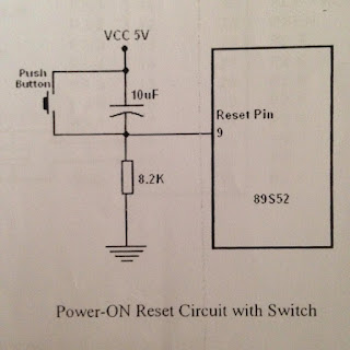
Set the reset button from pin 9 as shown in figure 3.
Make the controller in working order as show in figure 4, then connect an LED through resistor to pin of port 1.0
Set the reset button from pin 9 as shown in figure 3.
Make the controller in working order as show in figure 4, then connect an LED through resistor to pin of port 1.0
Write a program of ON and OFF LED by using timer 0/1 in assembly language.
Burn the assembly language program in microcontroller through universal programmer.
You can see th wave form on oscilloscope.
Circuit Diagram:
 |
| pic configuration of ATML 89S52 |
 |
| Attachment of crystall figure number 2 |
 |
| Reset button figure no.3 |
 |
| Working condition of microcontroller figure 4 |
 |
| LED connection |
Assembly Language Program :
ORG 00H
MOV P1,#0FFH
MAIN:MOV TMOD,#01H
MOV TH0,#00H
MOV TL0,#00H
SETB TR0
LOOP: JNB TF0,LOOP
CPL P1.0
CLR TR0
CLR TF0
JMP MAIN


0 comments:
Post a Comment